Stepper motor bluetooth serial driver
April 17, 2013 28 Comments
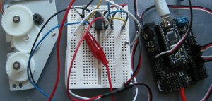
Above is the image of my very first attempt of driving this nice little bi-polar stepper motor (M35SP-11HPK) that I had salvaged from a broken Canon printer a while ago.
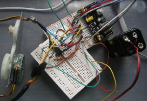
I have quickly put together a L293D H-bridge with an Arduino board and using the Stepper library was quite straight forward
For the impatient you can see a (probably boring) video right after the break…
Once I had it working, I immediately thought “wouldn’t it be nice to have a compact little driver board !?”.
The obvious choice for the micro-controller was one of the Attiny85 that I had just bought (the more I use them, the more I love them ! ) as I really like the minimalistic approach.
The novelty (for me) here is that even though I had already used various Attinys in the past, I had always programmed them using AVRStudio, whereas now I already had a working prototype with Arduino, and I was keen on using the same code…
Enter this wonderful project that I had heard a while ago on Make Magazine and wanted to try ever since.
The guys have managed to port the Arduino environment and some of the libraries and make them work on some of the Attinys, including the 85. You can find the code here.
The good news was that both the Stepper and the SoftwareSerial libraries were working just fine.
“Why serial stuff ?” you might ask… obviously because the easiest way of controlling this driver would be through a serial connection, so the role of the MCU would be to take the instructions received through the serial connection and transform them into commands for the L293D H-bridge.
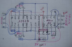
So I put together this schematic, with the help of these 2 pages (thank you guys !):
EDIT 21Apr2013 there are actually 2 things that have changed in the final version:
- I got rid of the voltage regulator, thinking it was the cause of the unreliability and random behaviour(it wasn’t, it was the noise on the wires and I dealt with it with capacitors as you’ll see later)
- as it is in the above picture, by default the motor will always be COASTING as the transistors will always keep 2 input pins high, and the ENABLE pins on the L293D are hard wired to high. This is not great as it uses current and heats up and H-bridges, and sometimes it’s simply what you don’t want… So I have modified the schematic and wired the VSS (the logic one not the one that goes to the motor) and the ENABLE1&2 pins of the L293D to P4 of the Attiny. So now the whole L293 is powered ONLY when the Attiny decides it needs to move the motor. The “BRAKE” command in the code was also added.
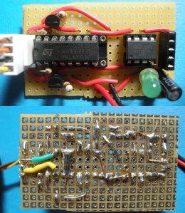
And here is the result:
By now everything was working almost too easily and mostly from the first try, so there had to be some challenge !
Before getting here I spent an inordinate amount of time debugging the board and not understanding why the heck it wasn’t working.
As you can see from the schematic, I initially had a L11117V33 voltage regulator, so that I can use 5V for the motor and 3.3V for the circuits. The idea behind this was to both “stabilize” the current for the circuits and remove all the unnecessary noise from the motor (I had this, probably wrong, idea that the voltage regulator would also act as some sort of filter…) and also have the same level of logic voltage as the one required by the Bluetooth serial adapter.
And yes, by that point I had also decided that if I were to use serial, it would be really cool to have wireless control… and what better way than using one of these really cheap JY-MCU (or similar) adapters that you can find on eBay for 5-6£ !?
Going back to my issues I went through removing the voltage regulator, de-soldering bits, changing the code, etc. … until I reached a “crazy” point where the “thing” was working when I connected the Attiny directly to the battery, but was not when it was connected to the onboard voltage… Now it might sound obvious now, especially for some of you that know more about basic analogue electronics, but it took me a while to realise that it was indeed the noise created by the motor on the power lines… this explained why the issues I was seeing were random.
As to why it was working when the MCU was connected directly to the battery, I can only speculate that the long wire was acting as some sort of capacitor filtering the high frequency noise…
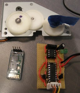
In any case, I was so relieved indeed when I realised that either an electrolytic 100uF or a ceramic 10nF solved the problem, that I ended up adding BOTH to the circuit, “just in case”… 🙂 You can see them in the low-right corner in the following picture, even though the smaller ceramic capacitor is hidden by the LED and the electrolytic one.
So here it is, the final product, I’m happy that it works beautifully, and that I can now remotely control this nifty little motor !
Here is the Arduino code running on the Attiny85:
/*
Bipolar Mitsumi M35SP-11HPK stepper, through L293D.
17Apr2013 Trandi
*/

#include <Stepper.h>
#include <SoftwareSerial.h>

#define STEPS_PER_REV 96 //360/3.75
#define SPEED_MIN 0
#define SPEED_MAX 300
#define PIN_ENABLE_MOTOR 4
#define MSG_MAX_SIZE 10
// structure of a command: 1 letter for the following options + number + CMD_END
#define CMD_SPEED 's'
#define CMD_CONTINUOUS 'c'
#define CMD_STEPS 'n'
#define CMD_BRAKE 'b'
#define CMD_END '#' //New line / Enter

// first 2 pins correspond to 1 coil, last 2 to the other coil
Stepper _stepper(STEPS_PER_REV, 2, 3);
SoftwareSerial _serial(1, 0); // RX, TX (2nd one is bogus as we don't have enough pins)
char _cmd;
char _cmdArg[MSG_MAX_SIZE];
int _cmdArgPos = -1; // current position in the text buffer. -1 if NOT in the middle of reading a message
boolean _continuous = true;
int _direction = 1;

long _lastHelp = 0;
void setup(){
 _serial.begin(9600);
 _stepper.setSpeed(SPEED_MAX / 3); // max 310 min 1
 pinMode(PIN_ENABLE_MOTOR, OUTPUT);
 digitalWrite(PIN_ENABLE_MOTOR, LOW); // motor disables <-> free wheel
}

void loop(){
 if (checkSerialData()){
 if(_cmd == CMD_SPEED){
 int sp = atoi(_cmdArg);
 if(sp == 0){
 _direction = 0; // _direction == 0 means no speed hence no movement
 }else {
 _direction = sp >= 0 ? 1 : -1;
 sp = abs(sp);
 sp = constrain(sp, 0, 100);
 sp = map(sp, 0, 100, SPEED_MIN, SPEED_MAX);
 _stepper.setSpeed(sp);
 }
 }else if(_cmd == CMD_CONTINUOUS){
 _continuous = true;
 }else if(_cmd == CMD_STEPS){
 _continuous = false;
 if(_direction != 0){ // _direction == 0 means no speed hence no movement
 int st = abs(atoi(_cmdArg));
 steps(st);
 }
 }else if(_cmd == CMD_BRAKE){
 _continuous = false;
 // simply enabling the motor will by default make it coast
 digitalWrite(PIN_ENABLE_MOTOR, HIGH);
 }
 }

 // in continous mode keep running 1 step at a time at the provided speed
 // _direction == 0 means no speed hence no movement
 if(_continuous && _direction != 0){
 steps(1);
 }
}

void steps(int steps){
 digitalWrite(PIN_ENABLE_MOTOR, HIGH);
 _stepper.step(_direction * steps);
 digitalWrite(PIN_ENABLE_MOTOR, LOW);
}
// Returns TRUE only, at the END of a valid command !
boolean checkSerialData(){
 boolean result = false;
 while(_serial.available()){
 int c = _serial.read();

 if(c == CMD_SPEED || c == CMD_CONTINUOUS || c == CMD_STEPS || c == CMD_BRAKE){
 _cmd = c;
 _cmdArgPos = 0;
 result = false;
 }else if(c == CMD_END){
 _cmdArg[_cmdArgPos] = NULL; // end of string
 _cmdArgPos = -1;
 result = true;
 }else if(_cmdArgPos >= 0 && _cmdArgPos < MSG_MAX_SIZE - 1){ //make sure we avoid buffer overflow !
 _cmdArg[_cmdArgPos++] = c;
 }
 }

 if(result){
 // confirm what we received to the sender
 _serial.print(" OK "); _serial.print(_cmd); _serial.print(_cmdArg); _serial.println();
 }
 return result;
}
I ended up learning more about capacitors than steppers :)… interestingly enough I had already seen plenty of times people adding capacitors when they used motors, but I always dismissed that as “one of those theoretical things than only happen in extreme conditions”…
As a final word, those that follow my blog (and read my long posts til the end 🙂 ) will know that the next logical step for this would be to have it hooked up to a little Android app, so that the whole thing can be remotely controlled from a phone !
To be continued…

How many steps does this motor (M35SP-11HPK) need for one turn?
Sorry, I have no idea, and don’t have access to it right now so that I could count…
Dan
Pingback: Bluetooth Stepper Motor controller | Fuzzy Hypothesis Online
Hello,
I work on this model of engine, I have many questions …
can i have your email for get the characteristic of this engine or a link to explain this engine because i find nothing about this
Thank you
Indeed, there’s almost no info out there about this motor.
All I know about it is in the post, feel free to ask any specific question here in the comments for the benefit of everybody…
Dan
I’m building a repstrap out of old printers, and I ripped the exact same stepper off a canon scanner. I’m considering it for my y-axis, but I can’t stand the noise (the sound, not electrical). Did you find any way to get rid of it?
Strange, I didn’t find it being noisier than other motors… it depends I think on the PWM setting, so you might want to play with its frequency so that it’s not close to the audible ones… but it’s just a guess.
Also, is that powerful enough for a 3D printer ??? The Nema17 that are normally used are much bigger and more powerful !
Dan
Pingback: ServoTester | Robotics / Electronics / Physical Computing
I like the bluetooth module you chose. For my senior year research project, I used the same module. Kinda wished more documentation was available on the module. I also found it interesting you used an Attiny for this project.
Yep, for a couple of pounds more it’s much more nicely packaged that the very basic one I used for my SPOKA project (https://trandi.wordpress.com/2012/01/13/spoka-night-light-controlled-from-and-android-phone/) which saves me some delicate soldering…
In my case I didn’t care about documentation that much, given that I used it with the default settings, but I agree if you want to change the bps rate, or even use the module without a microcontroller (it’s apparently possible to toggle pins on the module directly and monitor some basic sensors) then better documentation would be necessary… but then again this would easily double or triple the price of the device !
I’m an even bigger fan of the AtTiny45/85, I love minimalistic stuff 🙂
Dan
P.S. I like your FPGA posts on your blog, I keep wanting to start myself down this route, but never find the time… lol…
Hi,
I know it may seem obvious to you, but I would really appreciate a well screen-shotted guide to setting up the bluetooth.
I have spent the better part of a day trying just about everything to get bluetooth working and I am still at a loss.
I am on ubuntu, and I assume from your comment that your are, too. However, a guide for any OS would be helpful.
Thanks
Hi,
I’m actually using Windows as you can see in the video clip.
I also used Ubuntu for a different project where I had to pair with a similar Bluetooth device, and it worked.
I don’t remember exactly what I had to do, but there are countless tutorials online about how to set up Bluetooth under Ubuntu, and this is no different.
There’s no point in me doing again what’s already available out there…
Dan
Okay. No worries.
Do you remember what program you used to send serial commands via ubuntu?
I can get it paired fine. It’s the sending of commands that causes me grief.
Simple command line, something along the lines:
* cat /dev/rfcomm0 *
to read, or if you want to send data:*
echo Message to Arduino > /dev/rfcomm0*
Hope this helps ! Dan
Pingback: Bluetooth stepper motor driver from Hack a Day | Mike's Thoughts
Pingback: Bluetooth stepper motor driver | Cool Internet Projects
Pingback: Bluetooth stepper motor driver | Make, Electronics projects, electronic Circuits, DIY projects, Microcontroller Projects - makeelectronic.com
I’m interested in the setting up of the bluetooth connection, which your post glosses over a little bit. I think the adapter you’re using is similar to one on dealsextreme. under that JY-MCU name. I did a bit of googling and found datasheets and such, but it still looked complicated.
Specifically, how did the initial pairing work? Was there a default password? What was it? Did you manage to get AT commands working to change the password?
Thanks!
Hi,
Indeed, the main reason being that it was a non issue, it was really straight forward.
In Windows I simply clicked on the Bluetooth icon and chose something like “add new device” (I don’t honestly remember the exact steps, as you only need to do it the 1st time).
The default password is “1234”.
And no, I haven’t even tried to get into AT mode, as for that one you need to take one of the Bluetooth module’s pins up, and on the model I have it’s not clear if that pin is exposed on the side of the board or if I would have to remove the transparent plastic and solder directly on the tiny pins.
Hope this helps. What do you intend to use this for ?
Dan
I don’t have any direct plans, but it looks like a useful ‘building block,’ a component to go on a lot of other systems. Even if the range is short, seems useful for computer mcu talking!
Pingback: Bluetooth stepper motor driver | Daily IT News on IT BlogIT Blog
Pingback: Bluetooth stepper motor driver | Blog of MPRosa
Pingback: Bluetooth stepper motor driver | SIECURITY
Pingback: rndm(mod) » Bluetooth stepper motor driver
Pingback: Bluetooth stepper motor driver - RaspberryPiBoards
Pingback: Bluetooth stepper motor driver
Pingback: » Bluetooth controlled stepper motor Fuzzy Hypothesis Online