IrDA Enabling a PC or Microcontroller
January 9, 2010 6 Comments
This all started as a spin-off project for the Twitter to PSP project.

The final setup, in which the PSP is talking to an Arduino through the IR link (using IrDA protocol)
It turns out the “easiest” way of interfacing the PSP with a microcontroller is through the IR port.
There is actually only one other “resonable” option, through the PSP Volume Remote Controller, which is based on a serial line (normal RS232 protocol, but with different voltage). But given that this requires cutting of the cable and also creating a device to shift the voltage from [0,+2.5V] (to [0, 5V] for TTL or [-12,+12V] for “normal” UART) I, from the beginning, preferred to look into the IrDA communication, which had also the advantage of one less cable hanging…:)
If every you want to go down the volume remote controller road, here’s a very good ressouce : http://nil.rpc1.org/psp/remote.html
After some unsuccessful attempts to use directly a simple IR receiver (transistor) and to time the signals received, I turned to using a proper IrDA destined IR transceiver AND an IrDA controller, able to transform IrDA signals into normal UART, that a MCU is able to understand:
Components:
- VISHAY SEMICONDUCTOR – TFDU4300-TT1 – TRANSCEIVER MODULE, IRDA, INFRARED
- MICROCHIP – MCP2120-I/P – IRDA CONTROLLER, 2120, DIP14
- CRYSTAL, 7.3728 MHz, 18PF CL, HC49/U
- 2 x 18pF CAPACITORs for the crystal

The components, freshly received from Farnell (which I highly recommend for their promptness and free delivery)
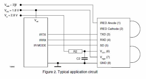
And here’s the schema I used:
Actually in the documentation, they recommend some extra resistor(s) and capacitor(s) for the TFDU4300, but it’s not mandatory (it might be in order to improve it’s effective distance, which indeed during my testing seemed to be more in the 20-30cm than 70-100cm as per their documentation…):
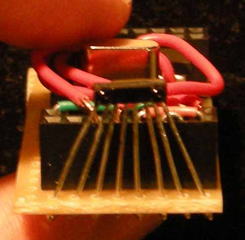
So that’s it! Except a VEEEERY painful soldering of the IR transceiver (it’s meant to be surface soldered by robots…) things are pretty simple and straight forward.
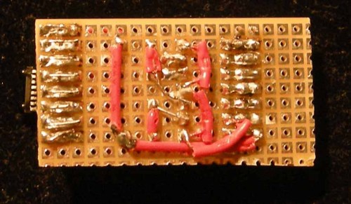
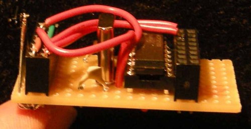
Here are the results :
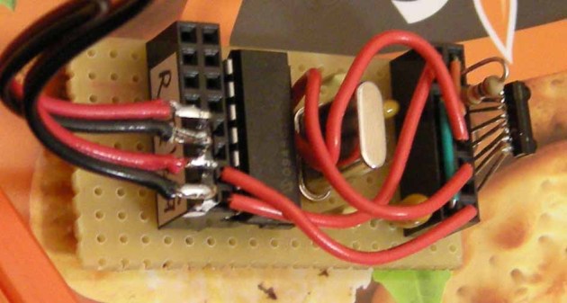
Final version with extra capacitors and resistors. NOT really necessary, except the big resistor between VLogic and VCC which lowers the Vlogic and makes the transceiver more sensitive.
And here’s the code used to test
Arduino
Using interrupts so that the MCU can do other stuff while waiting for IrDA communication!
#include <SoftwareSerial.h>
#include <WString.h>

#define rxPin 2
#define txPin 3

#define READ_TIMEOUT 300000 //nb of clocks. ROUGHLY equivalent to 500 millisecs
SoftwareSerial mySerial =  SoftwareSerial(rxPin, txPin);
char mData[100];
byte mPos = 0;
//SoftwareSerial.available() doesn't work, so use this + an interrupt
volatile boolean mSerialDataAvailable = false;

void setup()  {
 // define pin modes for tx, rx, led pins:
 pinMode(rxPin, INPUT);
 pinMode(txPin, OUTPUT);
 // set the data rate for the SoftwareSerial port
 mySerial.begin(9600);

 Serial.begin(115200);

 interrupts(); //enabled by default anyway, but just to be pedantic...
 attachInterrupt(0, dataInterrupt, CHANGE); // on pin 2
}

void loop() {
 Serial.println(millis());

 if(mSerialDataAvailable){
 detachInterrupt(0);
 for(byte i=0; i<mPos; i++) mData[i] = 0;
 mPos = 0;

 // listen for new serial coming in:
 int someChar = mySerial.read(READ_TIMEOUT);
 while(someChar != '#' && someChar >= 0){
 mData[mPos] = someChar;
 mPos++;
 someChar = mySerial.read(READ_TIMEOUT);
 }

 // print out the character:
 Serial.println(mData);

 mSerialDataAvailable = false;
 attachInterrupt(0, dataInterrupt, CHANGE);
 }
}

void dataInterrupt(){
 mSerialDataAvailable = true;
}
PSP
#include <pspkernel.h>
#include <pspdebug.h>
#include <pspctrl.h>

#include <stdlib.h>
#include <unistd.h>

#include <string>
#include <sstream>
using namespace std;

/* Define the module info section */
PSP_MODULE_INFO("IRDA Example", 0, 1, 1);
PSP_MAIN_THREAD_ATTR(THREAD_ATTR_USER);

/* Exit callback */
int exit_callback(int arg1, int arg2, void *common) {
 sceKernelExitGame();
 return 0;
}

/* Callback thread */
int CallbackThread(SceSize args, void *argp) {
 int cbid;

 cbid = sceKernelCreateCallback("Exit Callback", exit_callback, NULL);
 sceKernelRegisterExitCallback(cbid);

 sceKernelSleepThreadCB();

 return 0;
}

/* Sets up the callback thread and returns its thread id */
int SetupCallbacks(void) {
 int thid = 0;

 thid = sceKernelCreateThread("update_thread", CallbackThread, 0x11, 0xFA0, 0, 0);
 if (thid >= 0) {
 sceKernelStartThread(thid, 0, 0);
 }

 return thid;
}

/** MY CODE **/

#define printf pspDebugScreenPrintf

SceUID mSceUID;

int IR_Init( )
{
 return (mSceUID = sceIoOpen("irda0:", PSP_O_RDWR, 0));
}

void IR_Write(string data)
{
 //sceIoWrite(mSceUID, "test#", 5);

 data.append("#"); // tell the micro controller the end !
 if(sceIoWrite(mSceUID, data.c_str(), data.length()) != data.length()){
 printf("ERROR could NOT write  %s", data.c_str());
 }
}

int main(void)
{
 SceCtrlData pad;
 pspDebugScreenInit( );
 printf("\nIRDA Test Application\n");
 IR_Init( );

 string msg = "Wow: ";

 while(1){
 for (int i=0; i<255; i++)
 {
 pspDebugScreenSetXY(0,3);
 ostringstream tmpBuff;
 tmpBuff << i;
 printf("Sending  %s", (msg + tmpBuff.str()).c_str());
 IR_Write(msg + tmpBuff.str());

 sleep(1);

 // Refresh the PSP Button States
 sceCtrlReadBufferPositive(&pad, 1);
 // If Circle is pressed exit the Application
 if(pad.Buttons & PSP_CTRL_CIRCLE){
 sceKernelExitGame( );
 }
 }
 }
}





Hi,
Great blog! 🙂
I am wondering if you knew if this method (using the MCP21xx and/or Arduino) works for sending/receiving pictures or other files?
Also, do you know if it is possible to bypass the infrared transeivers (TFDU4300 in your case)?
The idea would be to connect two IrDA devices by wire, to avoid wasting power on IR LEDs.
I’ve seen “USB to IrDA” adaptors for PC but they cost a lot of money, they are bulky and I don’t know if they work with Linux, so I’m interested in a cheaper alternative. I don’t want to spent around 100 euros for something I’m not sure if it will work.
Thanks in advance,
Markus
Hi Markus,
Sorry for the late reply, yes you can very well send pictures/files over serial so you should be able to do it in this case too.
HOWEVER, you need the code/app on both sides to encode/decode the stream, and I don’t think it will be easy to find that, especially on the Arduino side…
Re connecting to IrDA devices by wire, maybe, but WHY ? Why not just using normal serial connection if you have access to the wires ?
Dan
Hi Dan,
Thanks for your reply.
So, the thing is that it is not clear to me what is the difference between IrDA and UART.
My understanding (from your post and your reply above) is that the MCP21xx chip is a sort of “phy” (IrDA) for UART (“phy” as in Ethernet phy, or USB phy, ie: a signal conditionner for a given physical medium so that an ethernet or USB controller can talk over such medium), in the sense that from the outside, it will behave just like an UART, and one can use minicom or other serial terminal program to use it, and, again from the outside, it would look like if the connection was just plain old wired UART (the “phy” in this case being wires). Do you see what I mean?
IIUC your reply, my understanding (above) is true, right?
Another reason I asked for this, is that if you search “IrDA to USB adapter” they cost over 60 dollars/euros, so I thought there is lots of intelligence/logic in them, but, again, IIUC your comment, they are not more than a FTDI + MCP21xx, right?
Regarding connecting IrDA by wire. My initial idea was what you said, connect directly, bypassing IrDA, the thing is that I have not found enough litterature to support the fact that I could just bypass it. Again, I thought that IrDA required lots of intelligence/logic.
If IrDA is just UART over IR, then yes, I guess I can probe the wires and see if I can get access directly to the UART.
Thanks again for your reply and your article!
Markus
Yes, as far as I remember the MCP21xx makes the IrDA look like any standard UART, the micro-controller has no idea what’s behind it.
Dan
On 28 April 2016 at 13:18, Robotics / Electronics / Physical Computing wrote:
>
Pingback: Lightweight software UART -> custom serial « Robotics / Electronics / Physical Computing
Pingback: Twitter – PSP (java) – Arduino (Peggy2) « Robotics / Electronics / Computer Science