Improve Wireless Doorbell
March 7, 2013 9 Comments
This is an unexpected project, that might prove one of my (very) few that are actually finished and useful ! 🙂
Yes, it’s about a cheap wireless doorbell that we’ve been having trouble with recently: it would stop working without notice due to the voltage from the batteries dropping below a certain value.
The initial solution was to replace 2 batteries with 3, which meant that it would “last” longer, but this made things even worse as we’d forget about it and after a month or two we’d realise after missing a delivery or something similar that the doorbell wasn’t working again…
So this was the perfect pretext for a small electronics project, centred around the idea of a simple voltmeter that would notify us when the voltage goes below a safe level.
This would most easily be done with a small micro controller that has an ADC.
For some reason I quickly decided that I also wanted the doorbell to count the rings, to be able to quickly see if we’ve missed anybody while away from home.
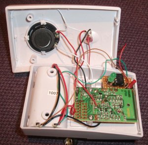
First step was to check the voltage ranges from the battery and also decide of a point in the original circuit where I could get a reliable signal for each ring:
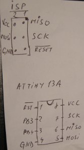
Then I came up with the following schematic:
As you can see, it’s really simple:
- 1 extra LED (could have used the existing one on the doorbell but didn’t want to interfere with its inner workings) to notify when the voltage gets too low AND if there were new rings since the last re-initialisation
- 1 switch to reset the count of the rings
- a simple voltage divider as the input would be 3-5V whereas the ADC reference on my MCU of choice is 1.1V
- and finally, the most important, the smallest MCU I had lying around, an AtTiny13A, which the more I use the more I like…
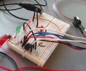
So let’s test the circuit see if it works:
It wasn’t easy to debug the code as there’s not hardware serial on the AtTiny and I don’t have a debugger board…
Do notice that I found a nice switch with a long red button, from this salvaged WiiMote:
Quite surprisingly, things seemed to work without too many issues, which is a first, especially that I used 3 interrupts and I’m notoriously bad at understanding how they work…:):
- the watchdog interrupt – to wake us from sleep every 8 seconds
- the external interrupt INT0 on a rising edge – to notify of a ring
- the PCINT0 pin change interrupt – to notify when the switch is pressed
You’ll notice that I didn’t really have to use so many interrupts, I could have used 1 or 2, or even none, if I didn’t care about some extra power usage (you’ll notice that I went crazy and even learnt about the sleep mode, which reduced idle current from about 4.5mA to about 0.5mA).
Here’s a summary of some quick measurements regarding the power saving in sleep mode (current in mAmps):
| LED on | LED off | |
|---|---|---|
| _delay_ms() | 9.5 | 4.5 |
| WTD timer | 9 | 3.5 |
| WTD timer + sleep mode | 6 | 0.5 |
However, I like this project as it ended up a nice and clean reference on how to use plenty of nice technologies on the AtTiny13A (probably the same as on most AtTiny and similar to other Atmel MCUs):
- various interrupts
- sleep mode
- analog to digital converter (ADC)
- simple digital output
- etc. …
So here’s the code, which I’m sure I’ll use in the future as reference for other AtTiny projects, let’s hope other people will find it useful too:
#define F_CPU 1200000UL      /* 9.6int Osc divided by 8 */

#include <avr/interrupt.h>
#include <avr/sleep.h>
#include <util/delay.h>

#define PORT		PORTB
#define PIN			PINB
#define DDR			DDRB

// User interface LED
#define LED_PIN		PB4
// Battery voltage measure analog input pin (through voltage divider)
#define VOLT_PIN 	PB3
// Momentary switch monitor digital input pin
#define SW_PIN		PB0

// Watchdog Interrupt for sleep mode
ISR(WDT_vect){
	// do nothing just wake up the MCU from sleep
}

volatile uint8_t ring_count = 0;
// External interrupt on PB1 - ringbell LED
ISR(INT0_vect){
	ring_count++;
}

// Interrupt on PB0 - switch
ISR(PCINT0_vect){
	// do nothing just wake up the MCU from sleep
}

void setup_watchdog_timer(){
	// prescale the Watchdog Timer - 8secs
	WDTCR |= (1<<WDP3) | (1<<WDP0);
	// enable Watchdog Timer interrupts
	WDTCR |= (1<<WDTIE);

	// use the Power Down sleep mode
	set_sleep_mode(SLEEP_MODE_PWR_DOWN);
}

void setup_interrupts(){
	// enable INT0 and all the PCINTx
	GIMSK |= ((1 << INT0) | (1 << PCIE));
	// The rising edge of INT0 generates an interrupt request.
	MCUCR |= ((1 << ISC01) | (1 << ISC00));
	// enable PCINT0 / PB0 - any change
	PCMSK |= (1 << PCINT0);
}

void setup_adc(){
	// select ADC3/PB3 (0 for MUX1 and MUX0)
	ADMUX |= ((1 << MUX1) | (1 << MUX0));
	// left adjust so that we just need to run the high 8 bits (ADCH)
	ADMUX |= ( 1 << ADLAR );
	// enable the internal reference at 1.1V (instead of Vcc as analog ref)
	ADMUX |= (1 << REFS0);
	// ADC enable and clock divide 1.2MHz by 8 for 150kHz sample rate (has to be between 50 and 200kHz)
	ADCSRA |= ( ( 1 << ADEN ) | ( 1 << ADPS1 ) | ( 1 << ADPS0 ) );
	// disable digital input on analog input channel to conserve power
	DIDR0 |= ( 1 << ADC3D );
}

// only the most significant bits, so it goes from 0 to 255
uint8_t get_adc(){
	// start the ADC Conversion
	ADCSRA |= ( 1 << ADSC );
	// wait for the conversion to be complete
	while( ADCSRA & ( 1 << ADSC ));
	// return the 8-bit left adjusted adc val
	return ADCH;
}

uint8_t is_sw_pressed(){
	// when SW pressed, the pin is 0 as connected to GND
	return ~PIN & 0x01;
}

void led_on(){
	PORT |= (1 << LED_PIN);
}
void led_off(){
	PORT &= ~(1 << LED_PIN);
}

void blink_long(){
	PORT |= 1<<LED_PIN;
	_delay_ms(500);
	PORT &= ~(1<<LED_PIN);
}
void blink_short(){
	PORT |= 1<<LED_PIN;
	_delay_ms(30);
	PORT &= ~(1<<LED_PIN);
}

void display(uint8_t value){
	uint8_t val = value;
	// only care about the 3 lest significant bits which are enough for up to 8 counts
	for(uint8_t i=0; i<3; i++){ 		if(val & 0x01){ 			blink_long(); 		}else{ 			blink_short(); 		} 		_delay_ms(300); 		val = val >> 1;
	}
}

int main(void){
	// enable pullups for input pins too
	MCUCR &= ~(1 << PUD);

	// LED
	DDR |= (1 << LED_PIN); // output

	// Voltmetre
	DDR &= ~(1 << VOLT_PIN); // input
	//PORT |= (1 << VOLT_PIN); // write 1 to enable internal pullup

	// Switch
	DDR &= ~(1 << SW_PIN);  // input
	PORT |= (1 << SW_PIN);  // write 1 to enable internal pullup - the SW is connected to ground

	setup_watchdog_timer();
	setup_interrupts();
	setup_adc();

	// enable global interrupts - must be done before going to sleep 🙂
	sei();

	uint16_t vcc = 0;
	while(1){
		sleep_mode(); // go to sleep and wait for WDT or INT0 interrupt...

		// 1. The SWITCH interrupt woke us
		if(is_sw_pressed()){
			// re-init the ring count
			ring_count = 0;
			blink_short();_delay_ms(60);blink_short();_delay_ms(60);blink_short();
		}else{
			// 2. The RING of WATCHDOG interrupts

			// the voltage divider has a 98.3kOhm and 21.9kOhm resistors
			// Vin = ADC/256 * Vref(1.1V)   #   Vcc = Vin * (R1+R2)/R1
			// final factor calculated empirically give voltage in deciVolts
			vcc = (get_adc() + get_adc() + get_adc()) / 15;
			// if below 3.1Volts then raise the alarm !
			if(vcc < 31){ 				led_on(); 			}else{ 				led_off(); 				// if there's been at least one interrup/bell ring -> display the number
				if(ring_count > 0){
					display(ring_count);
				}
			}
		}

	}
}

/*
Interrupt 0 Sense Control
ISC01 ISC00 Description
0 0 The low level of INT0 generates an interrupt request.
0 1 Any logical change on INT0 generates an interrupt request.
1 0 The falling edge of INT0 generates an interrupt request.
1 1 The rising edge of INT0 generates an interrupt request.
*/

/*
ADC Input Channel Selections
MUX1..0 Single Ended Input
00 ADC0 (PB5)
01 ADC1 (PB2)
10 ADC2 (PB4)
11 ADC3 (PB3)

ADC Prescaler Selections - These bits determine the division factor between the system clock frequency and the input clock to the ADC.
ADPS2 ADPS1 ADPS0 Division Factor
0 0 0 2
0 0 1 2
0 1 0 4
0 1 1 8
1 0 0 16
1 0 1 32
1 1 0 64
1 1 1 128
*/

/*
Watchdog Timer Prescale Select  - 128kHz OSCILLATOR
WDP3 | WDP2 | WDP1 | WDP0 # Number of WDT Oscillator | Cycles | Typical Time-out atVCC = 5.0V
0 0 0 0 # 2Kcycles 16 ms
0 0 0 1 # 4Kcycles 32 ms
0 0 1 0 # 8Kcycles 64 ms
0 0 1 1 # 16Kcycles 0.125 s
0 1 0 0 # 32Kcycles 0.25 s
0 1 0 1 # 64Kcycles 0.5 s
0 1 1 0 # 128Kcycles 1.0 s
0 1 1 1 # 256Kcycles 2.0 s
1 0 0 0 # 512Kcycles 4.0 s
1 0 0 1 # 1024Kcycles 8.0 s
*/
So now it’s time to put everything together…
Create a small strip-board:
Once the new little board was done, mount it nicely inside the original plastic box:
And the final product which I think looks quite clean, or at least by the standard of my other projects … :
In the middle you have the original red LED, to the left the added green LED and towards the top the red switch to re-initialise the ring count.
The way it works is:
- in normal mode, nothing happens
- when the batteries voltage drops below 3V, the added greed LED will light up continuously until I change the batteries
- when someone rings, the MCU will count that ring and then, every 8seconds will display the total count in binary format on the grid LED: a short blink for a 0 and a long blink for a 1
- when the switch is pressed the count of the rings will be re-initialised to 0
I hope you enjoyed my post, it’s definitely a quick and easy project, but surprisingly rewarding and interesting.
As usual, please don’t hesitate to leave your feedback in the comments.


how to find output signal from receiver ? i want to connect it to relay to drive sirine. and not use the melody.
Great project. I wonder though if showing the number of rings in binary format is the way to go. Would maybe be easier to just flash say 5 times for 5 missed calls, probably would be easier to follow, especially for the uninitiated. Nevertheless, great project
Hi, thank you for your comment…
Re the display in binary, this was never intended for the “uninitiated” 🙂
Pingback: Wireless doorbell battery monitor | Make, Electronics projects, electronic Circuits, DIY projects, Microcontroller Projects - makeelectronic.com
Pingback: Wireless doorbell battery monitor | Siecurity.com
Pingback: Wireless doorbell battery monitor | Daily IT News on it news..it news..
Pingback: Wireless doorbell battery monitor | Cool Internet Projects
Pingback: rndm(mod) » Wireless doorbell battery monitor
Pingback: Wireless doorbell battery monitor